Adding RGB ambient lighting to my VW Golf GTI
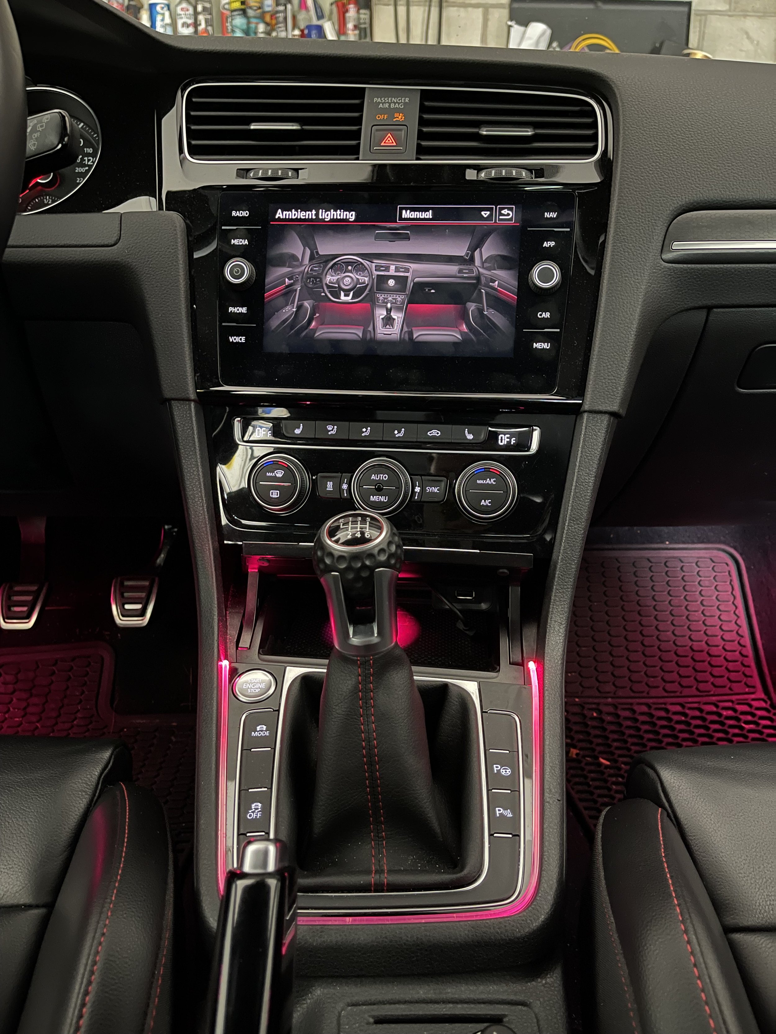
Ambient lighting user interface built-in to car’s settings
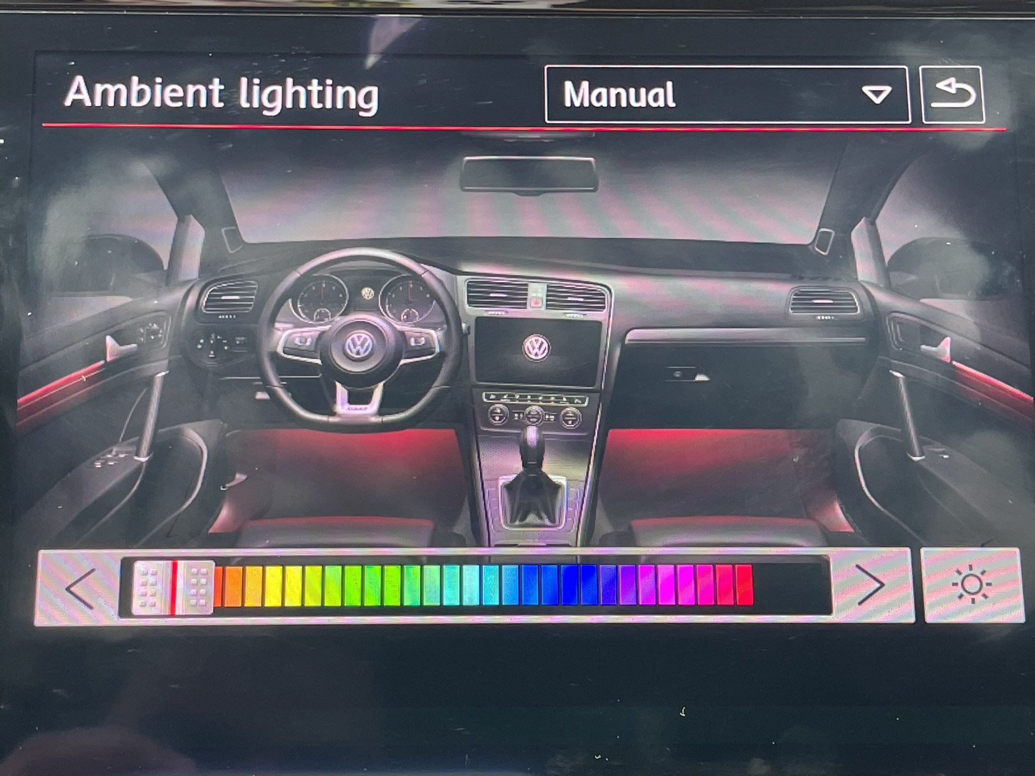
Hidden in the head unit software of every Golf is a user interface for multicolor RGB lights, as seen in the picture above. This Ambient Lighting feature is typically disabled and like many other features on Volkswagen cars can be “coded” and re-enabled by using a VW-specific scan tool plugged into the OBD2 port of the car. After seeing the ambient lighting in action on the Jetta (example here), I knew I had to get RGB lights in my GTI somehow. And after some research and time with the scan tool, I found how to enable the previously mentioned hidden Ambient Lighting menu.
The ambient lighting menu with 30 colors available to choose from
There was a bit of an issue, though.
Ambient lighting was never an option on a Golf in the US, and I’m not sure that it was available anywhere else. I could change the color in the picture of my interior on the screen, but as there were no actual RGB LEDs installed anywhere in the car, the door trim and footwells would stay red and white respectively, no matter what I set the color to.
And this is where the project began. If there were no lights available to retrofit, why not try making something myself?
Research
I figured that, even though the GTI was not built with the RGB LEDs in mind, there had to be some communication of the color happening within the car - when I changed the color in the Ambient Lighting menu, the gauge cluster also changed its theme color. This probably meant that the color data was being sent through the CAN bus between the two modules, the stereo and the gauges.
So, the first order of business would be to search the bus for the color data while I was changing the color in the car UI. I used a Raspberry Pi for this as it’s easier to set up and see what’s going on with it than a microcontroller. As well, from the car wiring diagrams, I found the most convenient place to hook into the CAN bus would be at the connectors to the AC controls.
Raspberry Pi 3 with CAN bus HAT attached, connected to the two CAN bus pins of the AC controls connector, +12V, and ground
Finding the Color Data
Using can-utils on the Raspberry Pi, I was able to see all the messages being sent on this CAN bus. (Side note: there are several buses in the car - this particular one is the Convenience CAN). There was so much data being sent that it was impossible to tell which of the messages contained the selected color.
I feel in these situations it’s good to think of the simplest way to find the data and start from there. What if the ambient lighting software in the car was simply sending the color, somewhere in the data, represented as its RGB value in hexadecimal - one byte red, one byte green, and one byte blue. Well, I got lucky, because that’s how it actually was sending the data! Using the OBD scan tool, I could program any of the 30 available ambient colors to a custom value. I picked 3 unique color data bytes such that when I searched in the CAN bus data, those 3 bytes would likely be unique and jump out in a search.
Just like that, after applying the color coding, setting up the Raspberry Pi to record CAN packets, and using the ambient lighting menu to pick my unique color, it took just one search on the data to find the message (in particular, the message ID) that contained the color data.
With this message ID, I could now program a microcontroller of my own to listen for this message on the CAN bus and change the color of an LED light to match! This was the first big step in integrating this system with the car.
A PIC microcontroller with an addressable RGB LED attached (WS2812, also called NeoPixel). The PIC is connected to the CAN bus using an MCP2562 CAN transceiver.
The CAN module on the PIC is set up to accept the ambient color message, read the RGB value, and set the color of the addressable LED to that color.
What about brightness?
Changing an LED to match the color in the car UI is great, but there was plenty more to think about. How about the brightness? When the car is off, the lights should fade out. When you unlock and open the door, they should come on. When you’re driving during the day and it’s sunny out, the lights should be off. If you’re driving at night, they should be on. If you change the color, the light should smoothly fade to the new color. The list goes on…
Making things even more complicated - the brightness of the footwells and the doors can be adjusted independent of each other.
It took more trial and error with cansniffer on the Raspberry Pi to find how the car was adjusting the brightness of the original LEDs. For the doors, it turned out to be pretty simple. A one-byte value was constantly being sent out that specified the brightness, 0 being off and 64 being fully on.
For the footwells, it was more complicated as I could not find a brightness value for them being broadcasted on the CAN bus. It was necessary to keep track of the status of the headlights, the footwell brightness set by the car’s ambient lighting menu, as well as a one-byte value that specifies the current status of the interior lights.
With all of this information gathered, I was ready to start working on the code!
Software + Hardware
I chose to use a PIC microcontroller after finding an application note from Microchip showing how to write a driver for NeoPixel (WS2812) RGB LEDs that’s all in hardware (link: AN1606 Using the CLC to Interface a PIC16F1509 and WS2811 LED Driver). The PICs I found also had a built-in CAN controller. Overall, this meant I could use just 2 chips to make this lighting system work: the PIC itself, and a CAN transceiver chip.
The software on the PIC generally works as follows:
The PIC receives power
All the peripherals are initialized - CAN controller, CLC module, SPI, DMA, and a few timers
A while(1) loop is entered
In every iteration, the software checks if a relevant CAN message was received
The software determines what to do using a state machine that represents the states of the car lighting as well as the current state of the RGB LEDs (for example, idle, fading down, fading up, and changing color)
When it’s determined that the LEDs need to change color and/or brightness, a timer is configured to trigger an interrupt about every 25 ms, changing the brightness slightly on each iteration. The interrupt ensures the microcontroller can still receive CAN messages during an LED brightness/color transition.
DMA is used to feed data to the SPI module, which combined with the CLC module, drives the LEDs all in hardware and ensures the timer interrupt can return as quickly as possible
Power Consumption
The amount of power being used by the ambient lighting system is important, given that when the engine is off, the system is running off the 12-volt battery of the car. The sleep and standby modes of the PIC microcontroller and CAN transceiver chip are used to bring the current down from 20-30 milliamps (12 volts) when idling to less than 1 mA when in sleep mode. A timer is used to detect when there is no activity on the CAN bus, then saves the current RGB color into flash memory and puts the PIC into sleep mode. When activity is detected again on the bus, the PIC is woken up by an interrupt from the CAN transceiver.
The power supply is a 90%+ efficient Adafruit 5V DC switching power supply.
PCB
It only took a couple prototypes using proto board to realize that trimming wires to the exact right length and cutting copper traces by hand is pretty tedious. I decided to make a PCB for this project and the learning curve ended up being 100% worth it. I used EAGLE to create a schematic and design the PCB. The resulting PCB was more compact than my prototypes, making it perfect for fitting behind the trim panels of the car. Not to mention, it was so much easier to solder it all together.
Adding lights to the doors and footwells
With the main board finished, the remaining work was to get the addressable RGB lights physically installed to replace the factory lights. I chose to replace the 2 footwell lights as well as the 3 lights in each front door. Thankfully, the mini-sized addressable NeoPixel LEDs ended up fitting essentially perfect in every location. In some cases, I had to add some padding or glue to keep them in place.
To connect the LEDs to the main board, I used PWM wire as it’s easy to find and order a whole set of them. This wire is typically used for connecting servos and motor controllers, but it was great for this application as well because like servos, the NeoPixel LEDs have 3 pins: signal, +5V DC, and ground.
Going beyond the factory lights
Drawing from parts used for servos and motors again, I used PWM splitters to add more lights in the storage compartment and through a fiber-optic I routed around the gear shifter. With this system, the only limit to how many LEDs can be connected is the total current they draw.
Demo
Future Work and Improvements
The system is fully functional and works well over long periods of time installed in the car. However, there are still areas that I’d like to revisit and improve upon.
Use surface-mount components instead of through-hole to shrink the board size
Refactor the state machine in the code to make it more clear
Start using connectors instead of 0.1” headers so the LEDs and board power can’t be plugged in backwards and are more securely attached


